Testing Spray Controllers
The spray controller diagnostic screen allows you to toggle the controller
LEDs and relays on and off, force the trigger and active output signals
on and off, and monitor controller input states.
The Spray Controller module LEDs and relays default to normally off
(relays open). During normal operation, the LEDs remain off and the relays
remain open during normal operation. When a fault occurs, the appropriate
LED lights and the appropriate relay closes. The LED and relay affected
return to their normal state when the fault is resolved.
NOTE: The failsafe mode can
be changed to closed, if desired, through the Nordson Service screen for
the spray controller. If this is done the relays will not open if a fault
occurs when spray controller power is lost or shut off.
Toggling LEDs and Relays
Use this procedure to toggle the LEDs and relays to make sure they are
functioning.
CAUTION: Shut
off the coating system before testing the Spray Controller relays. Testing
the relays with the coating system operating will generate an alarm and
shut down the system.
 Touch
the information and setup bar on the appropriate Spray Controller
faceplate.
Touch
the information and setup bar on the appropriate Spray Controller
faceplate.
 Select Spray
Controller Configuration from the drop-down menu.
Select Spray
Controller Configuration from the drop-down menu.
 Touch
the Diagnostics button at
the top of the Spray
Controller Configuration window.
Touch
the Diagnostics button at
the top of the Spray
Controller Configuration window.
NOTE:
To prevent an operator from accidentally tripping the relays and shutting
down the coating system, you must turn on the Test Mode before you can
use it.
 Touch
the Test Mode button toggle
it On. The switch backgrounds change from gray to green and the switches
move if necessary to show the current operating state of the LEDs
and relays. The spray monitor is now in diagnostics mode.
Touch
the Test Mode button toggle
it On. The switch backgrounds change from gray to green and the switches
move if necessary to show the current operating state of the LEDs
and relays. The spray monitor is now in diagnostics mode.
 LEDs
LEDs
 Relays
Touch the switches as necessary to set the LEDs and/or
relays to the desired state. The actual LEDs and relays on the spray
monitor will not change until you perform step 5.
Switch Status
 Touch the test buttons to test the LEDs or relays. To return the LEDs
and relays to their actual operating state, touch the button again.
Touch the test buttons to test the LEDs or relays. To return the LEDs
and relays to their actual operating state, touch the button again.
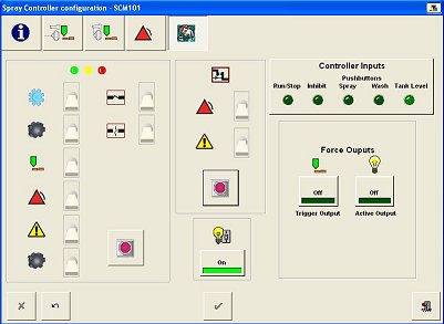
Controller Outputs

 Toggles the Trigger
Output on and off.
Toggles the Trigger
Output on and off.
Toggles the Active
Output on and off.
Use these buttons to test the functioning of the outputs.
Controller Inputs
The Controller Inputs indicators show the state of the inputs connected
to the controller. When the indicator is bright green the controller is
receiving a signal.
Run/Stop
Inhibit
Spray
Wash
Tank Level